OpenGL 2D Facade (5): Textures
In this post, I introduce OpenGL textures and use them to draw tiles from tilesets.
This post is part of the OpenGL 2D Facade series
Textures and UV maps
Textures are images stored on the GPU, and OpenGL uses them to draw primitives using colors from these textures. Contrary to what one can imagine, this is a fully 2D process.
Thanks to the rasterization, OpenGL computes a set of properties for each pixel of the screen, called fragments. For each pixel, OpenGL needs an RGB color to render it. Using colors per vertex as we did previously, the color of a pixel is a combination of vertex colors, depending on its location on the primitive.
In the case of texture, OpenGL also needs an RGB color for each pixel, and instead of combining vertex colors, it read it in the texture. Consequently, the question is: which pixel of the texture OpenGL should read? Here come UV maps: it is the set of 2D coordinates in the texture that defines the pixels to read.
An example
Let's take the following example:
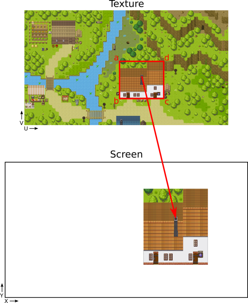
In our scene, we have a single quad: a rectangle in the right of the screen, and we want to texture it with a house.
To get this result, we must define a UV coordinate in the texture for each corner of the rectangle. For instance, the coordinates of the corner 'a' is (0.46, 0.44).
UV coordinates are also floating values (like screen coordinates), but they are between 0 and 1 (instead of -1 and 1). To compute them, divide pixel coordinates by the pixel width or height of the texture. For instance, the pixel coordinates of 'a' is (896, 480), and the texture size is (1920, 1080). As a result, the UV coordinates are u=896/1920=0.46 and v=480/1080=0.44.
Note: OpenGL UV vertical coordinates (so V in UV) are bottom-top, like the screen coordinates. So, if we follow this rule, the UV coordinates of 'a' is (0.46, 0.56). The image coordinates, on the contrary, are top-bottom. However, if you load the image without a flip, for OpenGL, it is reversed. As a result, to get the right V coordinate, we must reverse what is reversed! In other words, we can use top-bottom vertical coordinates.
If this note is not clear: in the following, I assume that we load images such that V coordinates are top-bottom, like in image editors.
Interpolation and Fragment shader
Now we see how OpenGL selects the pixel in the texture for each corner, but what about the others?
OpenGL does something similar to the vertex colors: it interpolates the UV coordinates for each pixel. For instance, if the pixel is in the center of the rectangle, then the corresponding UV coordinates are in the center of the UV rectangle in the texture.
This interpolation handles different aspect ratios. In the example with the house, the width of the UV rectangle in texture (in red) is larger its height. The corresponding rectangle on the screen has, on the contrary, a height larger than its width. OpenGL interpolates the UV coordinates such as the house fill all the rectangle surface.
In the fragment shader, we receive these interpolated UV coordinates. For the pixel corresponding to the current fragment, we have to choose its color. In the case of textures, this color is the one at the UV coordinates: it is simple as that. Note that OpenGL provides a function that returns the color of any pixel of texture given UV coordinates.
Update the code with textures
Now, let's update the Python code in the previous post to display the house like in the example.
Load an image
First of all, we need to load an image. There are many available libraries for that, and I selected a popular one: Pillow.
At the beginning of the program, import the Image class from the Pillow package (named PIL):
from PIL import ImageThen, load and convert the texture image:
image = Image.open("samplemap.png")
assert image.mode == "RGBA"
imageArray = np.array(image)
Line 1 loads any image (png, jpg, most image formats are supported) and returns a PIL.Image class instance.
Line 2 checks that the pixel format is (Red, Green, Blue, Alpha). Alpha encodes the opacity of a pixel. I will always use this format to support transparency, but also because it eases many processings.
Line 3 converts the PIL image into a Numpy array.
Image size and pixel order
The "samplemap.png" image has a width of 1920 pixels and a height of 1080 pixels. If you execute the following expression:
print(image.size)It shows the size of the PIL Image: (1920, 1080). It is consistent with the size of the image.
Then, if you print the shape of the corresponding Numpy array:
print(imageArray.shape)It displays (1080, 1920, 4), so (image height, image width, RGBA). It looks like the conversion transposes the image. It is not the case: this is the result of the pixel order in memory.
If we want to access the pixel of coordinates (x,y) with Numpy, we have to use the expression imageArray[y, x]. If we ask for the size of the first item of the array:
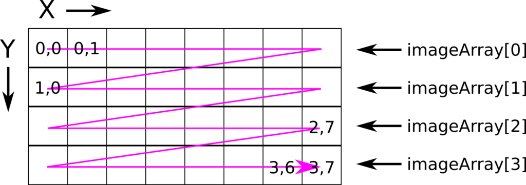
print(imageArray[0].shape)We see on the console: (1920, 4), which corresponds to the top row of pixels in the image. It means that the first pixel of the array is the top left one, then the one on its right, and so on.
I did a small scheme that could help to understand this:
Texture object
The imageArray Numpy array contains our texture image in the CPU memory. We have to copy it to the GPU if we want to use it in shaders.
We can create an OpenGL texture and sets its pixels and properties in the following way:
textureID = glGenTextures(1)
glPixelStorei(GL_UNPACK_ALIGNMENT, 4)
glBindTexture(GL_TEXTURE_2D, textureID)
glTexParameteri(GL_TEXTURE_2D, GL_TEXTURE_BASE_LEVEL, 0)
glTexParameteri(GL_TEXTURE_2D, GL_TEXTURE_MAX_LEVEL, 0)
glTexParameteri(GL_TEXTURE_2D, GL_TEXTURE_MIN_FILTER, GL_NEAREST)
glTexParameteri(GL_TEXTURE_2D, GL_TEXTURE_MAG_FILTER, GL_NEAREST)
glTexImage2D(GL_TEXTURE_2D, 0, GL_RGBA, image.size[0], image.size[1],
             0, GL_RGBA, GL_UNSIGNED_BYTE, imageArray)
Line 1 creates a new texture; it's like all the glGenXXX() we already saw.
Line 2 defines how we align row memory addresses when copying from the CPU to the GPU. In our example, we use RGBA colors, so 4 bytes: each row memory address is always a multiple of 4. This value is the default one; I set it because I want to be 100% sure, but also to show you this feature.
Line 3 is another glBindXXX() function that sets the context to a specific object; in this case, the texture we want to work on.
Lines 4-7 defines properties using the glTexParameteri() function. The two first ones tell that we have a single mipmap level (we don't need mipmap for 2D rendering), and the two last ones tell that we want no color interpolation in the texture.
The last line call glTexImage2D() to copy the texture colors to the GPU:
- The first argument
GL_TEXTURE_2Dtells that we are working on the currently selected 2D texture; - The second argument
0sets the texture for mipmap level 0; - The third argument
GL_RGBAdefines the internal pixel format. In the case of RGBA there is no approximation; - The next arguments
image.size[0]andimage.size[1]are the width and height of the texture; - The sixth argument must be
0; - The next arguments
GL_RGBAandGL_UNSIGNED_BYTEis the pixel format of the data we are sending to the GPU. In this example, RGBA where each value is encoded using an unsigned byte; - The last argument
imageArrayis the buffer with all values.
Mesh data
For the vertices and faces, I create a single quad in the right of the screen (you can move or resize it if you want):
vertices = np.array([
     [0.0, 0.5],
     [0.0, -0.25],
     [0.75, -0.25],
     [0.75, 0.5]
], dtype=np.float32)

faces = np.array([
    [0, 1, 2, 3]
], dtype=np.uint)
faceCount = faces.shape[0]
For the UV coordinates, I first note the coordinates of the house from an image editor:
x1, y1 = 896, 480
x2, y2 = 1312, 832
Then, I normalize them:
u1 = x1 / image.size[0]  # divive by width
v1 = y1 / image.size[1]  # divive by height
u2 = x2 / image.size[0]  # divive by width
v2 = y2 / image.size[1]  # divive by height
Finally, I create a Numpy array from these coordinates:
uvMap = np.array([
    [u1, v1],
    [u1, v2],
    [u2, v2],
    [u2, v1]
], dtype=np.float32)
Vertex Array Object
In the previous Vertex Array Object (VAO), there were three Vertex Buffer Objects (VBO): vertices, colors, and faces. We use the same vertices and faces, and replace the colors by the UV map.
There is no significant difference, except that there are two values per vertex instead of three:
glBindBuffer(GL_ARRAY_BUFFER, uvVboId)
uvMap = np.ascontiguousarray(uvMap.flatten())
glBufferData(GL_ARRAY_BUFFER, 4 * len(uvMap), uvMap, GL_STATIC_DRAW)
glVertexAttribPointer(1, 2, GL_FLOAT, GL_FALSE, 0, None)  # 2 instead of 3
Vertex shader
The vertex shader is similar to the previous one, except that we copy the UV coordinates instead of the colors. Note that the UV coordinates are 2D (vec2) instead of 3D (vec3):
#version 330
layout (location=0) in vec2 vertex;
layout (location=1) in vec2 inputUV;
                   out vec2 outputUV;
void main() {
    gl_Position = vec4(vertex, 0.0, 1.0);
    outputUV = inputUV;
}
Fragment shader
Here is the new fragment shader:
#version 330
in vec2 outputUV;
out vec4 color;
uniform sampler2D textureColors;
void main() {
    color = texture(textureColors, outputUV);
}
There is a new input variable named textureColors. The uniform keyword means that this is the same value for all fragments. The sampler2D refers to the data set with GL_TEXTURE_2D.
The processing in the main() function calls the texture() built-in function. Given a texture and a UV coordinate, it returns a color. With our current settings, it is the color of the pixel nearest to the UV coordinate.
Final program
In the next post, I'll show how to use these texture to draw a tile and correct aspect ratio.